
Written by Mohammad Rajabalinejad*
Abstract—Safety is often seen as a requirement or a performance indicator through the design process, and this does not always result in optimally safe products or systems. This paper suggests integrating the best safety practices with the design process to enrich the exploration experience for designers and add extra values for customers. For this purpose, the commonly practiced safety standards and design methods have been reviewed and their common blocks have been merged forming Safety Cube. Safety Cube combines common blocks for design, hazard identification, risk assessment and risk reduction through an integral approach. An example application presents the use of Safety Cube for design of machinery.
Keywords—Safety, safety cube, design, product, system, machinery
I. Safety in Engineering Design Practice
THIS paper extends the scope of the conference paper [1]. In the engineering design process, safety is often considered as one of the performance indicators, hopefully among the important ones. As explained elsewhere in e.g. [2], the primary indicators for engineering performances are cost, time to market, and quality. Next to these, the engineering design practice is formulated by several steps starting from analyzing the problem, identifying requirements, generating ideas and concepts, embodying the chosen concept followed by detail design and testing [3]. Other widely accepted approaches, e.g. the V model in Systems Engineering, follow comparable patterns [4]. In this process, safety is often treated as a requirement that must be addressed through the processor as one of the indicators need to be addressed. Furthermore, safety-related techniques are often applied during and after the concept formation where details are preferably known. Common safety-related practices e.g. Preliminary Hazard Analysis (PHA) are performed to inform stakeholders about possible hazards or risks. Failure Mode and Effect Analysis (FMEA) is commonly used for exploring the possible failure scenarios, assigning failure probabilities, and analyzing the effects or consequences.
To represent the hierarchy of faults or subsequent events, Fault Tree Analysis (FTA) or Event Tree Analysis (ETA) are commonly used. The essence of these methods is based on component failure; a system failure is presented as a logical chain of events or faults. Methods like Fishbone, Cause & Effect diagram, or Root Cause Analysis focus on the relationship between hazard and possible events. To estimate the likelihood of these events, Probabilistic Risk Assessment (PRA) methods, Bayesian Belief Networks (BBN) or Incident Tree Method (ITM) [5]may be used. Those methods often assume that if a product does as intend to do, there is no failure and the product will be safe. In this context, reliability is thought to be like safety and the applied tools become incapable of capturing a situation that is unsafe but not initiated with a failure. The shortcomings of this assumption are becoming more obvious when systems become complex [5]. The next section summarizes the problem.
II. Problem Statement
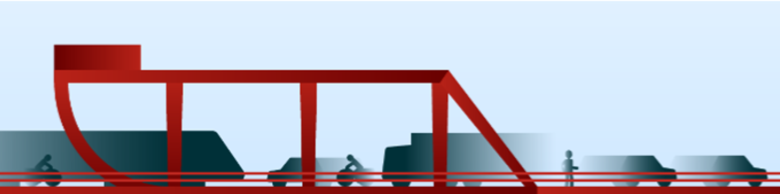
While designers focus to create a thing that must fulfill the customer needs, they also must think about foreseeable misuse scenarios or malfunctions. The constraint on time or other resources may push them to form a quick belief about the safety of their designs which might not be true. For example, a quick look at Fig. 1 may form the concept of three connected pipes in the mind which is not true. This is an example that how quickly designers may think about the proper functions and proper use of products rather than the misuse or malfunction scenarios.
Daniel Kahneman in the book “Thinking, fast and slow” [6]highlights this dilemma in general context. In fact, the commonly practiced patterns for designers, recommended by best practices, are built such that they encourage designers to think fast when they are thinking of functions or solutions and they do not make vacant space for designers to think about misuse or malfunction scenarios [3]. As a result, designers might think slow while exploring unexpected scenarios for their own designs. To address this problem, safety must get more space through the design process [7]. This study explores the possibility of building a “safety space” in the design process. For this purpose, first, the building blocks for design, risk, and safety need to be identified as discussed next.
III. Building Blocks for Design and Safety
A. Common Building Blocks
There are similar building blocks used for the design process and safety management process. To find these common building blocks for design and safety, references of best practices have been studied for systems safety [8], systems engineering [4], the safety of machinery [9], and requirements engineering [10]. Systems engineering offers proven techniques for integrating the main building-blocks and managing risks. The system safety standard is the oldest common-practice looking into system safety principles. The system safety standard presents the DoD (Department of Defense of the USA) approach for eliminating hazards, where possible, and minimizing risks where those hazards cannot be eliminated [8]. This Standard Practice covers hazards as they apply to systems, products, equipment, and infrastructure throughout design, development, test, production, use, and disposal. Also, the international standard ISO12100, a seminal reference for the safety of machinery, identifies major categories for the safety assessment of machinery.

Comparing the above-mentioned practices, there are three common blocks (elements) that must be considered in every design or safety analysis process. These are system, environment, and people as shown in Fig.2. Focusing on these three blocks, systems engineering, and risk management work together to ensure proper hazard recognition and management during system design, implementation or operation.
Therefore, it is obvious that the system of interest (SoI) is of primary focus for designers. The system has interfaces with (connections to) environment or other systems (the so-called super-systems) and is made of subsystems or components. Furthermore, the system interacts with people (e.g. operation or use). This is further discussed in the next section.
B. System and Operation
ISO12100 prescribes three major categories for the safety assessment of machinery which are operation, physical structure, and functions. The structure is a prerequisite of proper operation and use. While this ISO standard focuses on the current systems, it is inevitable to think about the experience and future expectations. This has been implicitly (and sometimes explicitly) indicated in standards but has an explicit role in the design.

C. Experience and Future Trend
Experience and future insight enable design for the present. Designers need to consider influences of time not only during the full lifecycle but the past and future generations. This not only inspires designers, offers them rich information, and give them further insight, but also is requested by safety standards. Furthermore, looking into the design or operational experience from the past, documenting the past accidents or incidents, and thinking about probable future use, or future misuse, are parts of the standard safety practices. Meanwhile, looking into future changes in the environment and the history of product development enables developing products or system that better adapts to their environmental changes. It is widely accepted that recognition of future trend plays a role in success [11].
Therefore, designers must have access to past systems and consider future developments. Learning from failures is only possible if there is access to earlier failures and a way for recommendations to future changes. For designers, the time element is to be considered as well. To give more focus to this, these elements need to be discussed in time spans before, during and after the lifecycle (or in-service). This suggests that the past information about the basic three elements for design and safety, which are system, environment, and people, should be easily available and accessible for designers.
IV. Safe Design
The design of products (machinery or systems) can be defined as the creation for doing intended functions and operations (use). This is summarized in three pillars of structure, function, and use in e.g. [9]. In the design process, however, there is often no explicit analysis of malfunction or misuse as discussed earlier in this paper. As a remedy, risk assessment and risk reduction must be a part of the design process [12]. In fact, if the risk is unknown, it is less likely to be managed in the proper way. If the risk is recognized, a designer can plan for removing the hazard. If not possible to remove the hazard, the designer can control and manage the risk by safeguarding or other complementary measures. Therefore, proper implementation of risk analysis in the design process alters is likely to improve safety.

Safe by design find the risky situations and overcome circumstances where (failure in) structure, (mal)function or (mis)use to cause harm to humans, environment, or property. Therefore, the safe by design process emphasizes both the working structure and failed structure, the proper functions, and malfunctions, and finally the proper use and misuse through design. The outcome creates specific space for identification of hazards leading to risk and safety management plans altering the design for more safety.
V. Safety Cube
Safety Cube presents the principal elements for design and safety integrally. This cube can generate different views. Visualized through Fig.4, a description of several views of the safety cube follows.
- The system view presents the system of interest (SoI), its environment (or super-system), and its components (or sub-systems). In principle, this covers the system, its subsystems, (user)interfaces and competing or cooperating systems. The interfaces among these components and their environment, failures in components or interfaces, and the chain of physical reactions are presented by this view.
- The operation view presents the use of system structure or functions in practice. The Interaction of the system with people (or other systems) is an important aspect of the system described here in terms of operation or use. This interaction is often present at all various levels of system, super-systems, and subsystems. Next, to use, a critical view on foreseeable misuse is important. For example, scenarios for transportation, installation, operation, and recovery process might happen differently, and not exactly according to the user expectations.
- Identification of a proper set of requirements and functions are among the critical performances for systems as well as safety engineers. States of the system and fault recognition modes are examples of this. Furthermore, expectations, recommendations, or requirements for future design gives a valuable set for future designs. These are presented through the functional view.
- The time view presents changes across the time axis. While the SoI for the present time is the primary focus for designers, it is inevitable to explore the history of the system development (lessons learned) and consider future developments. While normally the information about the past (ex-generation) should be available, the implicit or explicit information about the future trend is needed. Further explanations of these views are provided through an application example.
VI. Example Application
A typical design for machinery is presented here in this paper to show the safety and design-related views made by a safety cube. Table 1summarizes these views for the design of machinery. The information presented in this table are example considerations for the implementation of ISO 12100 and achieving safety-related certificates.
The first three rows of Table 1present the structural elements of the system, their interfaces with each other and the environment, and their possible failures. The third column presents the system of interest in the present time, and the other columns highlight the experience and future expectations.
The second-three rows of this table focus on the operation of the system, or its use and misuse. The experience for e.g. transportation, installation or operation of the system or the future trends e.g. minimal maintenance operation help a more-robust design.
The third-three rows of Table 1highlight the functions, malfunctions, or requirements for the system such as start-up or states of failure. At the super system or subsystem level, this can be for example housekeeping functions or disturbance in power supply. Functional faults that were (or were not) tolerated, unscheduled maintenance or disturbance, or recovery process are among the functional lessons that can be learned. Based on future trends, one may expect e.g. interaction with internet (IoT), remote operation, automatic fault recognition, self-repair and/or self-recovery. As a results, the information needed for design and safety assessment is collected and presented integrally through Safety Cube.
Table 1. Physical system, its use and functions in past, present and future.
| Past | Present (In use/life time) | Future | |
| Structure/ failure in structure | |||
| Environment or super-systems for SoI | Environment of ex-machine in service | Environment of machine in service | Environment of future machine in service |
| System of interest (SoI) | Drawing of previous machines | Machinery specification | Expectations for next generation |
| Subsystems or components of SoI | Component failures of ex-machine in service | Components of machine in service, wear out | Strategic changes in future components |
| Use/ misuse | |||
| Environment or super-systems for SoI | Transportation, installation or assembly | User specification, information for use | Digitally supported services |
| System of interest (SoI) | Accident, incident or similar machinery | Different machine operating modes | Keep the machine running all the time |
| Subsystems or components of SoI | History of damage, noise, vibration, etc. | Different intervention procedures | Low maintenance operations |
| Functions/ malfunctions | |||
| Environment or super-systems for SoI | Power supply distribution | Housekeeping, environmental requirements | Functions demanded by IoT or smart environment |
| System of interest (SoI) | Functional faults: (not)tolerated | Start-up, possible states, fault-finding | Remotely controlled operation |
| Subsystems or components of SoI | Unscheduled stops and recovery | Disturbance in power supply | Self-repaired, self-maintained |
VII. Conclusions
Safety is often not explicitly present in the design process commonly used by practitioners or engineers. As a result, they may quickly form beliefs about the safety of their designs which have not been tested and might differ from reality.
To create more space for safety in the design process, common blocks between safety and design have been identified and combined resulting in Safety Cube. Safety Cube creates space for safety (and so for risk assessment and control plans to alter the original design if necessary) through the design process. Furthermore, it generates different views for designers, systems engineers, or safety engineers. These views enrich the exploration experience for designers, practitioners, or engineers and add value to the final design. An example application for the design of machinery and implementation of ISO12100 is successfully presented and further utilization of this technique is recommended.

Interact with the safety cube through this link.
References
- M. Rajabalinejad, “Incorporation of Safety into Design Process: A Systems Engineering Perspective,” in ICSSE 2018 : 20th International Conference on Safety and Systems Engineering, Paris, France, 2018, vol. VIII, pp. 1366-1368: WASET.
- M. Rajabalinejad, G. M. Bonnema, and F. J. A. M. v. Houten, “An integral safety approach for design of high risk products and systems,” presented at the Safety and Reliability of Complex Engineered Systems Zurich, Switzerland, 7-10 September, 2015.
- G. Pahl, W. Beitz, J. Feldhusen, and K.-H. Grote, Engineering Design A Systemmatic Approach. Springer, 2007.
- C. Kevin Forsberg and C. Michael Krueger, “Systems Engineering Handbook A Guide For System Life Cycle Processes and Activities.” 2007, p.^pp. Pages.
- C. A. Ericson, Hazard Analysis Techniques for System Safety. John Wiley & Sons, 2005.
- D. Kahneman, Thinking, fast and slow. Macmillan, 2011.
- N. J. Bahr, System Safety Engineering and risk assessment. CRC Press, 2014.
- MIL-STD-882E: 2012 Department of Defense Standard Practice System Safety, 2012.
- EN-ISO 12100:2010 Safety of machinery – General principles for design – Risk assessment and risk reduction, 2010.
- E. Hull, K. Jackson, and J. Dick, Requirements Engineering. Springer, 2011.
- J. Hesket, “Past, Present, and Future in Design for Industry,”Massachusetts Institute of Technology Design Issues, vol. 17, no. 1, 2001.
- M. Rajabalinejad, “Modelling and Prioritization of System Risks in Early Project Phases,” International Journal on Advances in Telecommunications, vol. 9, no. 3-4, 2016.
*Dr. Mohammad Rajabalinejad is an Assistant Professor at the Faculty of Engineering Technology, University of Twente, The Netherlands (e-mail: M.Rajabalinejad@utwente.nl).